


Fiber Cement Board Plant Layout Design: Follow the Material from Mill to Packing


A workable Fiber Cement Board Plant Layout Design begins with a specific board and the sequence of material transformations needed to manufacture it. The buyer should know whether the plant will use Hatschek or Flow-on formation, the target board dimensions, the proposed raw materials and curing route, and the site conditions before approving building works. A polished three-dimensional factory rendering can make machinery look coordinated while concealing insufficient transfer space, inaccessible equipment or a curing hall that cannot receive completed loads. Zhonghong offers equipment for mineral preparation, automatic dosing, slurry storage, fiber-cement forming, waterjet cutting, stacking, selected pressing processes, steam curing, board separation, sanding, trimming and automation. Its machinery range and engineering services provide real starting points, but the plant footprint and utility requirements must be designed for the actual customer.
Imagine an investor who has already purchased an industrial building with columns and an existing service yard. Another investor can choose the plot and building geometry to suit the equipment. The first has to work within constraints; the second can design them out early. Both need a material-flow drawing that shows what happens from raw-material arrival to accepted finished boards, not merely a collection of machine rectangles.
Walk the site from raw-material receiving toward slurry preparation
The first part of the factory handles materials before any board exists. How mineral inputs arrive and move toward preparation affects unloading, storage, dust and material-transfer requirements. The site should allow the proposed feed route without creating unnecessary movement across finished-product or operator areas. The design must be based on the material actually purchased, because a plant grinding local raw minerals may need a different preparation arrangement from one buying ready-prepared ingredients.
Ball milling and incoming mineral storage require a consistent feed plan
Zhonghong’s Ball Mill is offered for mineral preparation relevant to fiber-cement and calcium-silicate board production. Whether it belongs in a plant depends on the feedstock and approved process. A factory that receives silica-bearing material requiring grinding may need space, foundations and service connections for that operation. A plant buying suitable prepared inputs might allocate its floor area differently. A layout should not include a mill solely because it appears in an example production-line diagram.
Consider a location where bulk materials arrive by truck but loading access is limited. The engineer must decide how feed can reach the preparation area without interrupting other operations. The supplier should specify the actual equipment dimensions and site requirements for the machinery offered; no universal mill capacity, dust-control rating or foundation loading is published for all Zhonghong projects. Those values belong in approved project drawings.
Dosing, slurry storage and the former need short, defined interfaces
The Automatic Dosing System meters constituents for an approved production formula and slurry concentration. A Slurry Storage Tank holds prepared material between stages to support the forming process. These are different tasks. Their relative placement must be designed around the intended slurry and transfer route, including appropriate access for inspection and servicing. A layout with a visually convenient tank location can still be unsuitable if the process connection to the former has not been defined.
Where the plant makes several board products, the engineering team should consider how an approved recipe change affects material already in the system. The website does not establish an automatic tank-cleaning or universal formulation-change function. A layout should leave practical provisions for the actual process rather than assume that an automated recipe selection solves every material condition. Process responsibility and equipment connections must be described before construction.
The wet-end layout must preserve fragile sheets through each change of state
After slurry preparation, the plant begins manufacturing a sheet. Zhonghong lists a multi-cylinder Hatschek Forming Machine and a Flow-on Forming Machine using controlled slurry distribution and dewatering. They do not represent identical mechanical layouts or feed requirements. The chosen technology affects where supporting equipment and operators need to be positioned, and it should be selected against the intended board and raw-material trials before the final building arrangement is approved.
The former, waterjet cutter and stacker should be drawn as one sequence
A continuous formed layer becomes individual green boards at the high-pressure Waterjet Cutting System. The Board Stacker then uses servo-controlled handling to position and organize them. The line drawing should indicate the sheet’s support from the former through cutting and onward, not merely put the three machine names beside one another. A poorly supported green board can be damaged before it reaches any curing equipment.
Suppose a plant expects two commercial board lengths. The cutting position may change, but the downstream support and stacking arrangement also need to be checked. A suitable layout considers the actual product mix rather than assuming that all dimensions pass through the same transfer without adjustment. The supplier should state which boards have been included in the design and which future variants would require engineering review.
Pressing and mould-plate separation create additional material streams
Some higher-density board routes may include Zhonghong’s Hydraulic Press. The company’s Stripping Machine separates boards from mould plates using suction lifting and servo-controlled travel. These are product-specific operations; not every factory requires the same combination. Where used, the plant layout must show what enters them and what leaves, including any supports or plates that return toward earlier production stages.
A drawing showing only boards travelling forward can miss the path of reusable mould plates. If returning supports share congested routes with green sheets, the factory may experience waiting time that a larger former cannot remedy. The design should distinguish those flows and assign the necessary handling equipment. A machine schedule that includes a press or stripper without a corresponding material route is not yet a complete production layout.
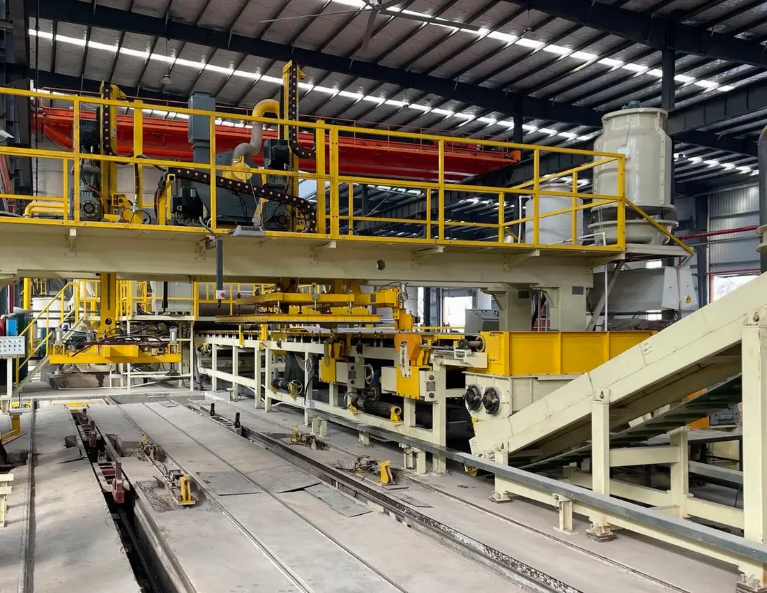
The curing hall changes the rhythm and space requirements of the factory
Steam-curing equipment often processes prepared loads rather than a continuous moving web. Zhonghong offers an Autoclave Curing System for applicable board products and a Shuttle Car for transferring trolleys between stations. The layout must show how completed loads are assembled, transported, treated, removed and moved toward board separation. A vessel’s nominal dimensions do not determine plant output or the floor area needed for supporting equipment.
Autoclave loads need movement and service space, not only vessel space
An investor should request a project-specific load plan showing board sizes, supports and the movement of material into and out of the curing area. Access for safe operation and servicing must be coordinated with the actual pressure equipment and site conditions. Applicable pressure-vessel and installation requirements depend on the destination and ordered equipment; the current company catalogue does not establish a universal approval or curing cycle for every factory.
Imagine a plant that can form and stack material reliably but has no efficient means of preparing the next autoclave load. Moving the main vessel closer to the former may not solve the staging or trolley-transfer problem. The engineer should calculate the process and handling arrangement together. The factory’s capacity model must account for the intended board and realistic load operations, not only a headline square-metre output from another installation.
Curing discharge should lead toward the Board Splitter without crossing wet routes
After treatment, the Board Splitter separates cured boards from curing pads and stacks sheets for later processing. Its output should have a defined route toward finishing, while supporting pads may need recovery or reuse. The layout should distinguish these paths from the vulnerable green-board movement earlier in production. A congestion problem after curing can create a factory-wide bottleneck despite a reliable forming section.
A brownfield extension may have little room for ideal linear routing. In that case, the owner must supply accurate building dimensions and ask the engineer to demonstrate an acceptable material-flow solution. The presence of Roller Conveyors and Shuttle Car equipment in Zhonghong’s range provides possible functions to discuss, but their selection depends on whether material moves as sheets, stacks or whole trolleys.
Finishing and packing need a layout based on the board’s sales specification
Not every board requires identical post-curing treatment. Zhonghong’s Sanding Machine addresses cured-board surface and thickness work, the Grinding & Chamfering Machine prepares edges, and the Board Cutting Machine makes final dimensional cuts. A plant may include one or several of these stages depending on the product. The finishing hall should be organized around the accepted output rather than the complete list of available machinery.
Surface and edge operations should not create repeated board handling
A decorative-facing sheet may need more surface treatment than a plain backing board. The line designer should determine which surfaces and edges are inspected and which machinery performs the required operation. If boards must repeatedly travel between cutting, sanding and edge-processing stations without a clear sequence, unnecessary handling and transfer risks may increase. A product-specific drawing can reduce these movements.
A distributor’s factory may also need to process several sizes and keep them separated during finishing and packing. The layout should allow for the real product mix and an identification point where finished sheets are approved. The public company information does not establish a fixed automated packing machine or capacity for every board grade. Where packaging equipment or additional controls are required, those items must appear in the actual project schedule.
Dust and service zones are part of usable factory space
Mineral grinding, cured-board cutting and sanding can produce dust or waste depending on the process. A responsible plant design must assess extraction, material collection, safe access and maintenance needs for the installed equipment. Industry safety principles explain these design considerations, but do not prove that any specific Zhonghong collector, filtration system or performance figure is included without confirmation.
An engineer should also consider access around control cabinets, conveying equipment and working machines. A layout optimized only for squeezing machines into the smallest footprint can become difficult to maintain. The owner should ask which spaces are required by the ordered equipment and which are reserved for safe servicing or later product changes, instead of treating every unoccupied area as wasted capacity.

| Factory zone | Layout question to resolve |
|---|---|
| Mineral receiving and preparation | Can feed reach the mill and dosing equipment without crossing finished-product traffic? |
| Forming and wet cutting | How is the vulnerable green sheet supported across the cutter and stacker? |
| Autoclave handling | Where are loads prepared, treated, unloaded and transferred for separation? |
| Finishing and inspection | Which surface, edge and dimension operations does the intended board actually require? |
Make the layout contractually useful before foundations are built
A supplier’s concept drawing is not the same as an installation-ready engineering package. The owner should identify which drawings need approval, who supplies civil and utility information, which parts of the building are the customer’s responsibility and when the machinery layout becomes frozen for fabrication. Zhonghong describes site survey, process design, equipment manufacturing, electrical automation, installation and commissioning services; the order must specify which are included for the particular project.
A dimensioned process flow is more useful than a rendered factory view
A practical drawing should locate actual machines and board routes, including receiving and discharge conditions. It should show relevant service and maintenance access and identify the interfaces between equipment suppliers where responsibilities differ. For a new project, those documents guide civil preparation. For a retrofit, they reveal where old equipment or building structures constrain the design. Changes after foundations are complete can be expensive, so the buyer should agree a controlled review before construction advances.
The whole-line planning article explains the board-specific process, while the plant supplier guide addresses site and contract questions. The equipment directory lists the actual machine families that should be placed on the drawing. A meaningful layout uses all three kinds of information rather than substituting one for another.
The first commercial board is the best final check of the factory flow
Before approving the complete installation, the investor should be able to trace one agreed board from raw-material preparation through forming, handling, treatment, finishing and packing. Each station should have a defined input and output, and operators should know what happens when the next station cannot receive material. The detailed acceptance procedure must be developed against the actual product, not a generic drawing of an ideal factory.
The right plant layout is the one that gives machinery a practical relationship to each other and to the site. It should support the board the business will sell, allow the required utilities and maintenance, and make later manufacturing or product changes understandable. If the design cannot explain those relationships, it is too early to approve foundations simply because the drawing looks complete.